ENGR210
LED/MQTT/Flask
Project 4
Due: Sunday, February 15th
Overview
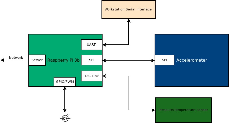
In this project, you will be adding an LED to your system that you can control through MQTT. You will be creating a class that allows you to set the PWM duty cycle and frequency for a GPIO pin attached to an LED. Additionally, you will be modifying your sensor_node.py code to enable changing these values though MQTT.
Resources
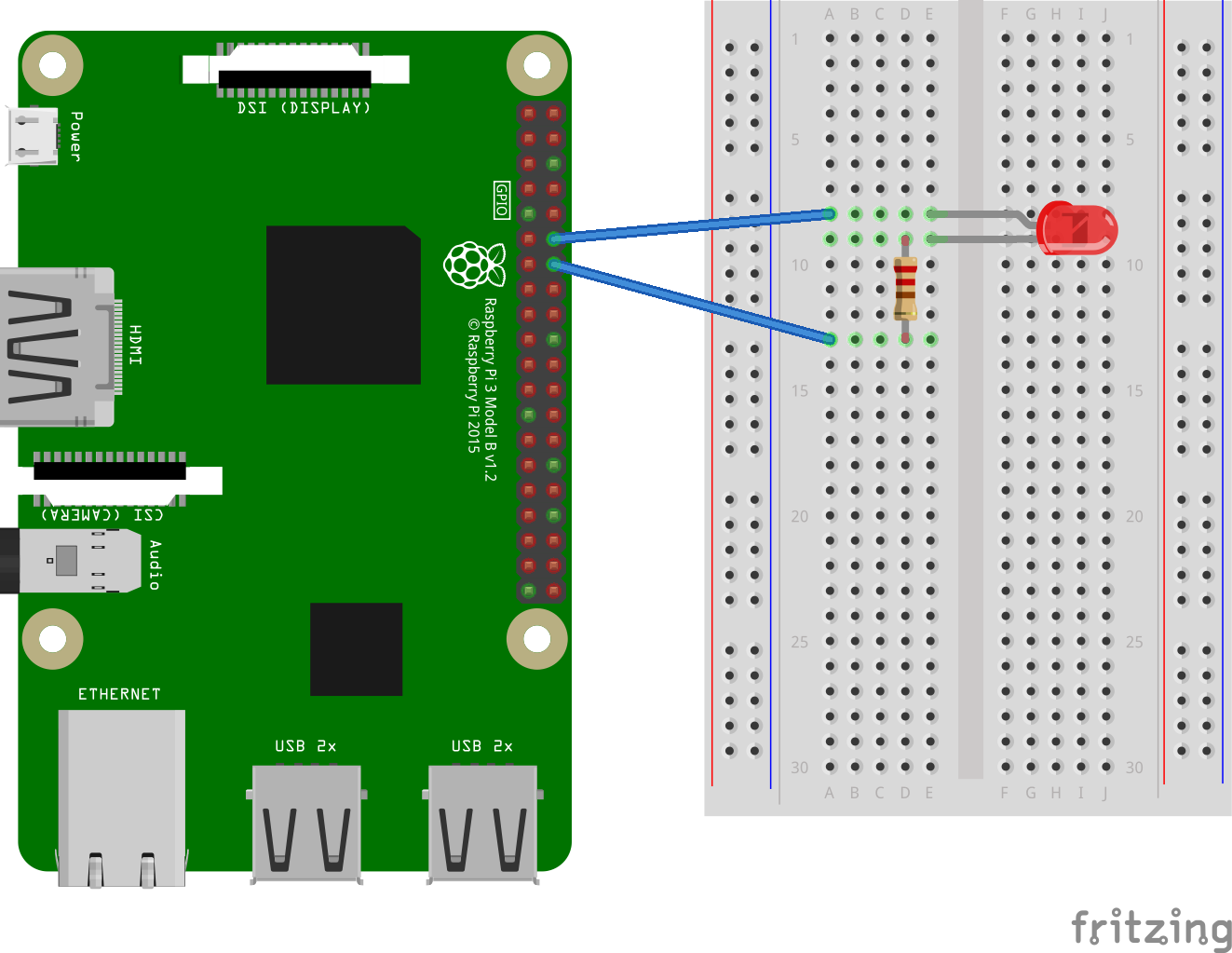
LED Wiring
Connect your LED and resistor to pin GPIO18. The LED and resistor are connected between GPIO18 and ground.
Led_Driver Class Development
Create a class named “Led_Driver” that allows a pin to be controlled as a PWM. The following template will give you a starting point for designing this class. Name this file led_driver.py and add it to the same folder as your sensor_node.py code.
#!/usr/bin/env python3

import RPi.GPIO as GPIO

class Led_Driver:
	def __init__(self, pin, frequency=100):
		self.pin = pin
		self.frequency = frequency
		self.duty = 0
		GPIO.setwarnings(False)
		GPIO.setmode(GPIO.BCM)
		GPIO.setup(self.pin,GPIO.OUT)
		self.pwm_out = GPIO.PWM(self.pin,self.frequency)
		self.pwm_out.start(0)

	def on(self, duty=100):
		self.pwm_out.ChangeDutyCycle(duty)
		self.duty = duty

	def off(self):
		self.pwm_out.ChangeDutyCycle(0)
		self.duty = 0

	def change_frequency(self, frequency):
		self.pwm_out.ChangeFrequency(frequency)
		self.frequency = frequency

	def __str__(self):
		outstr = f"Pin = {self.pin}\n"
		outstr += f"Frequency = {self.frequency}\n"
		outstr += f"Duty = {self.duty}\n"
		return outstr


if __name__ == '__main__':
	bcm_pin = 18
	freq = 100
	led = Led_Driver(bcm_pin, freq)
	input("Initialized, Hit a Key for 100% Duty Cycle: ")
	led.on(100)
	print(led)
	input("Hit a Key for 75% Duty Cycle: ")
	led.on(75)
	print(led)
	input("Hit a Key for 50% Duty Cycle: ")
	led.on(50)
	print(led)
	input("Hit a Key to change Frequency to 5 Hz with 50% duty cycle: ")
	led.change_frequency(5)
	print(led)
	input("Hit a Key to change back to 100 Hz with 50% duty cycle: ")
	led.change_frequency(100)
	print(led)
	input("Hit a Key for 25% Duty Cycle: ")
	led.on(25)
	print(led)
	input("Hit a Key for 0% Duty Cycle: ")
	led.off()
	print(led)
	input("Hit a Key to exit ")
Led Duty Cycle and Frequency MQTT Topics
Use the on_connect method that was included in the code template from lab 3 to subscribe to two topics named “sensors/your-sensor-serial-number/led/duty” and “sensors/your-sensor-serial-number/led/frequency”. You should add the following subscription line to your on_connect function.
topics = [(f"sensors/{sensor_id}/led/duty",0),(f"sensors/{sensor_id}/led/frequency",0)]
client.subscribe(topics)
Uncomment the printing of the topic in the on_message function. Start the sensor_node.py program. Use mosquitto_pub to send messages to the led topics that you subscribed to above. Confirm that you are getting these messages.
Controlling the Led Driver using MQTT Messages
Import your led_driver into the sensor_node.py code then Initialize your led. When an MQTT message comes in related to the led, make the requested change to the led state.
In the loop where you are publishing sensor data, add one additional publication line to indicate the status of the led. This code assumes that your led instance is named led. If it is not, change the code accordingly.
client.publish(f"sensors/{sensor_id}/led/status",f"duty:{led.duty},frequency:{led.frequency}")
Using mosquitto_pub, demonstrate that you can set the duty cycle of the LED at 0%, 50%, and 100%. Also demonstrate that you can set the frequency of the led to 100 hz and 5 hz.
What to turn in (DUE 2/16 11:59PM)
1) Working code:
- You and your partner should work to complete this module and commit it to your repository. When you are satisfied with the code, go to canvas and submit the commit link.
- You and your partner should also demonstrate your working code (Controlling LED through MQTT commands along with the updated publications that include led status) to one of the TAs present. Alternatively, a video of your functioning code may be submitted to canvas, but this method of submitting is not recommended unless you are sure of the accuracy of your code.
- You should use mosquitto_sub and mosquitto_pub on silo to subscribe to all the messages from your sensor and to send led instructions to the Pi.
2) Individual Contributions:
-
List down the accomplishments of each member of the group. You should use a
MarkDowntable for this purpose. The table should be formatted similar to the following:Date Time Contributor Accomplishment 2/8/2024 3:15 pm Nicole Completed on_message code 2/8/2024 4:30 pm Aidan Completed on_connect code 2/8/2024 4:45 pm Caleb Helped debug code 2/8/2024 5:45 pm Jesus Wrote LED control code
Both team members should submit to the canvas.