ENGR210
Project 9: Serial Peripheral Interface (SPI)
Due: Friday, May 2nd
Overview
In this lab you will construct a Serial-Peripheral Interface (SPI) link between the Basys3 FPGA and a Raspberry Pi.
Introduction
You are in luck. We finally automated the Vivado project creation step. Please open a terminal on the 4111 machines and type the following instructions to get started:
git clone https://github.com/ENGR210/P9_SPI.git
cd P9_SPI
make setup
vivado vivado/vivado.xpr
That should create the vivado project for you and start vivado with the project open.
Assignment Description
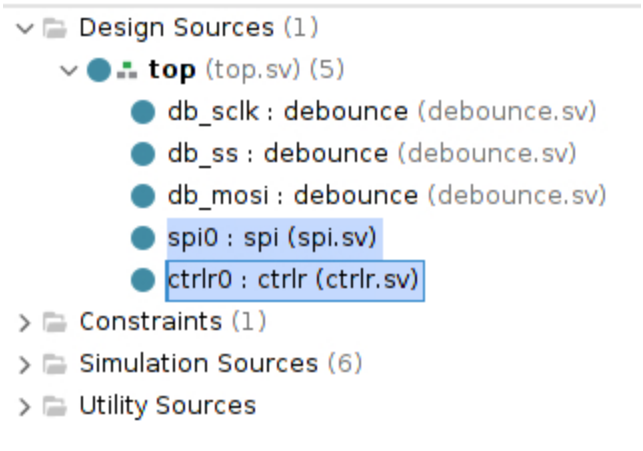
Under the project’s “Design Sources”, you should see spi.sv and ctrlr.sv. These files need modification:
SPI
The definition and a partially-complete stub of the SPI module need to be extended to implement SPI. See Appendix I below for additional implementation details.
module spi(
    input               clk,
    input               rst,

    //SPI interface
    // Signals to/from the Raspberry Pi
    input               sck, //Serial Clock
    input               ss,  //Serial Reset Not
    input               mosi, //Serial input from Pi
    output              miso, //Serial output to Pi

    //
    //Hardware interface
    //Signals to/from the rest of the Basys3
    //

    // this is the parallel input from the Basys3
    // it's what gets sent out over the SPI on the next
    // transaction
    input        [7:0]  din,

    //this is the parallel output to the Basys3
    // it's what was recieved from SPI over the last
    // transaction
    output logic [7:0]  dout,

    //this tells the Basys3 that a SPI transaction is ongoing.
    // it should go high at the FIRST rising edge of a SPI transaction
    // and stay high until the LAST falling edge of the SPI transaction
    output logic        busy
);
Ctrlr
The definition and a partially-complete stub of the Controller module need to be extended to implement the control interface. See Appendix II below for additional implementation details.
module ctrlr(
    input                   clk,
    input                   rst,

    //GPIO interface
    input           [15:0]  switches,
    output logic    [15:0]  leds,

    //
    //SPI Command Interface
    //

    //Used to indicate that the data from SPI is currently
    // valid and wont change randomly
    // i.e. there is no ongoing SPI transaction
    input                   dvalid,

    //input from SPI
    // coming from the Raspberry Pi
    input           [7:0]   din,

    //output to SPI
    // to be sent to Raspberry Pi
    output logic    [7:0]   dout
);
All remaining files in the Vivado project do not require any modification
Testbenches
For this project, we provide you with all needed testbenches
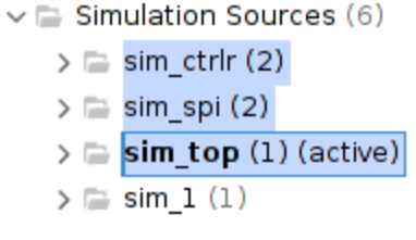
Sim_ctrlr: This tests just thectrlr(controller) interfacesSim_spi: This tests just the SPI interfaceSim_top: This tests the top-level design, including both the ctrlr and SPI sub-modules
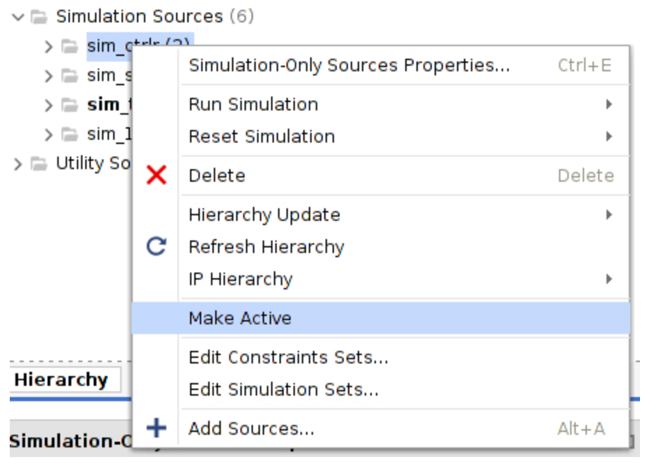
To switch which simulation is active, right click and select ‘make active’:
Raspberry Pi
Hardware Connections
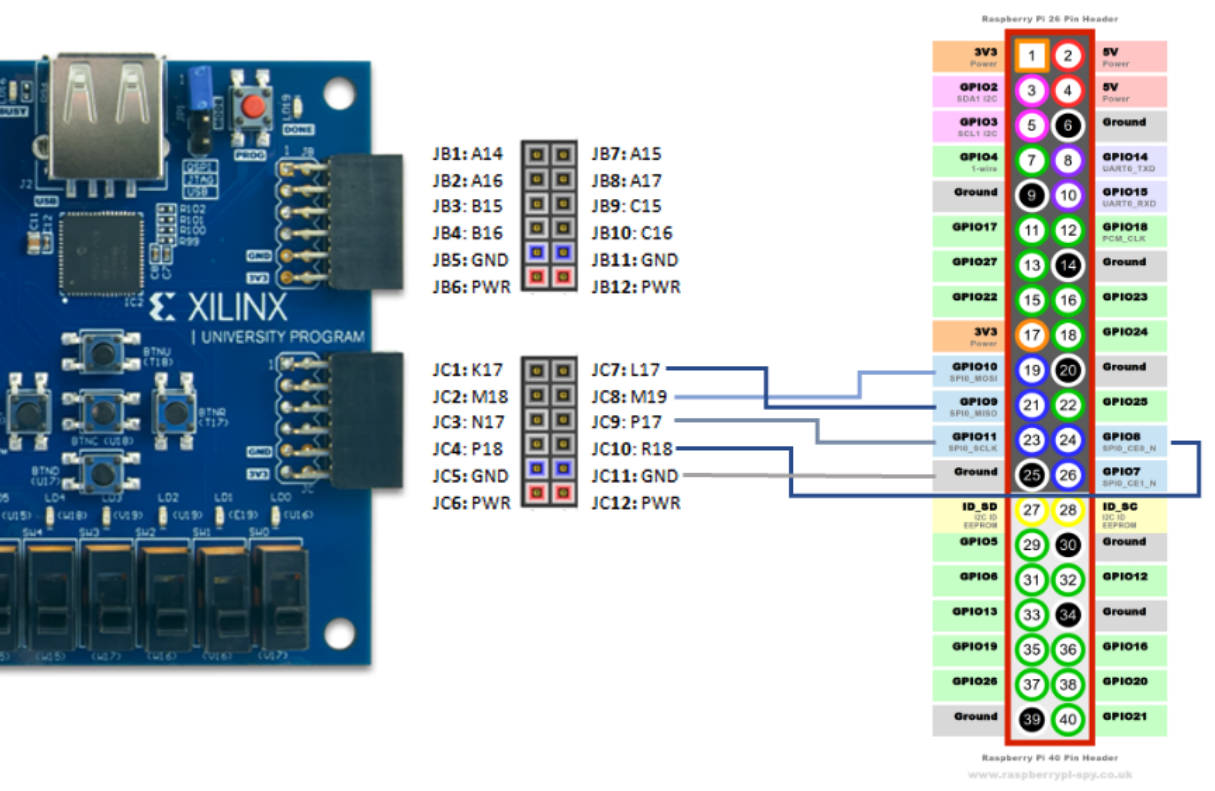
Once passing all testbenches, connect your Raspberry Pi to your Basys3 using the following pin mappings:
| SPI Signal | VIVADO SIGNAL | Basys3 Pin | Raspberry Pi Pin |
|---|---|---|---|
| SCLK | JC[6] |
JC9 | 23 |
| MOSI | JC[5] |
JC8 | 19 |
| MISO | JC[4] |
JC7 | 21 |
| SS / CE0_N | JC[7] |
JC10 | 24 |
| GND | - | JC11 | 25 |
Python
Once the wiring is complete, open a terminal on your Pi and type the following:
git clone https://github.com/ENGR210/P9_SPI.git
cd P9_SPI/pi
python3 spi.py
Evaluation
The evaluation will have two steps:
- Submit your FPGA code to the autograder
- Synthesize your design, download it to the FPGA and do a demonstration for the TA.
Autograder (60%)
Log on to https://autograder.luddy.indiana.edu and submit your testbench code.
Demonstration (40%)
Program your FPGA with your SPI controller and demonstrate your working system to the TA. You will not receive full points until the TA has approved your demonstration.
MAKE SURE YOU HAVE “$display(“@@@Passed”);” AT THE END OF YOUR TESTBENCH! AND $fatal IN THE APPROPRIATE SPOT! Otherwise some bugs may not pass!
Appendix I: SPI Interface
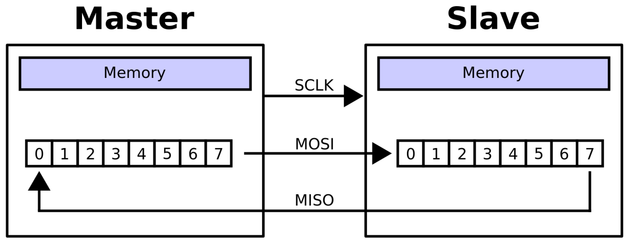
Conceptually, SPI is a shift register between two devices. In our case, the Rasperry Pi is the Master and the Basys3 is the slave in the in the figure below.
A SPI transmission looks like the following figure:
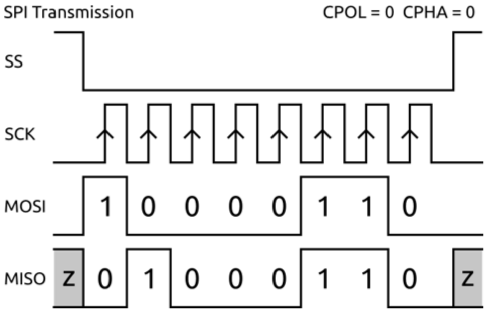
When writing Verilog for the SPI slave interface, here are a few major items to note:
- The INCOMING data (
MOSI) is captured on the RISING edge ofSCLK. - OUTGOING data (
MISO) is updated on the FALLING edge ofSCLK. - In class, data is transferred from MSB to LSB. MSB is the most significant bit (
data[7]). LSB is the least significant bit (data[0]).
Because MOSI uses the RISING edge and MISO uses the FALLING edge, both are transmitting ‘at the same time’ (but on their respecting clock edges).
Explanation of Signals
The SPI module contains the following signals:
| Signal | Explanation |
|---|---|
clk |
The Basys3’s 100MHz clock |
rst |
The Basys3’s reset signal |
sck |
The SPI’s Serial Clock. This is ~10MHz |
ss |
The SPI’s Slave Select signal. When this is high, the SPI is inactive (reset). When it is low, the SPI is active. |
mosi |
This is the SPI’s Master-Out-Slave-In signal. This signal comes from the Raspberry PI and comes into the Basys3 |
miso |
This is the SPI’s Master-In-Slave-Out signal. This signal comes from the Basys3 and goes to the Raspberry Pi. |
dout |
This is the SPI’s 8-bit parallel data output to the remainder of the Basys3. This signal is connected (through top) to the controller interface. It is used to drive new data to the controller. |
din |
This is the SPI’s 8-bit parallel data input from the Basys3. This signal is connected (through top) to the controller interface. This allows the controller to drive new data out over SPI. |
busy |
This signal is used to tell the controller that a new byte has been received over SPI. It should go high for 1 cycle after the completion of the SPI transmission. |
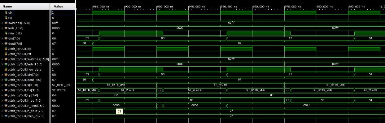
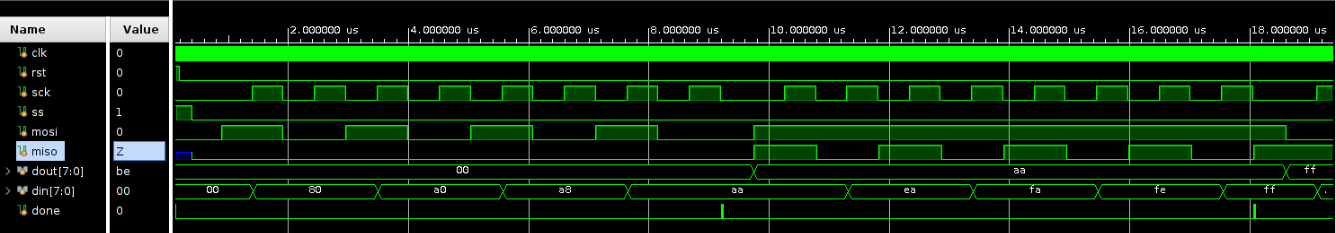
Example Waveform
Appendix II: Controller Interface
The Controller (or Ctrlr) interface implements a 2 byte read/write interface that allows SPI to interact with the Basys3’s switches and LEDs.
Address Mapping
The Controller makes the switches and LEDs accessible via an address mapping detailed below. The Read and Write sequences (detailed below) are used to access the various addresses.
| Address | Mapping | Type |
|---|---|---|
7'h00 |
chip_id (8'h7) |
Read-Only |
7'h01 |
switches[7:0] |
Read-Only |
7'h02 |
switches[15:8] |
Read-Only |
7'h03 |
leds[7:0] |
Read/Write |
7'h04 |
leds[15:8] |
Read/Write |
Note: Writes to addresses with Read-Only type should be ignored
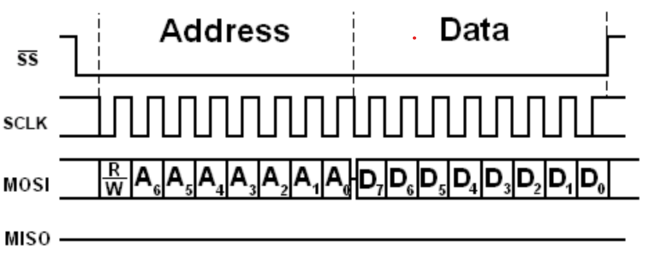
Write Sequence
For Writes, the Pi (Master) writes a new value to the Basys3 (slave) using a 2-byte sequence. The first byte sent is the address and the second byte is the data. For a write, set R/W = 0. For a write, the Basys3 can respond back with any values (including all 0) over MISO. Both unneeded bytes are ignored.
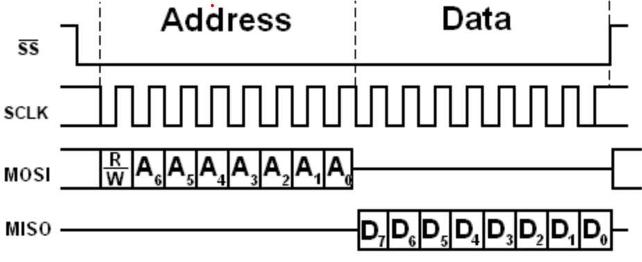
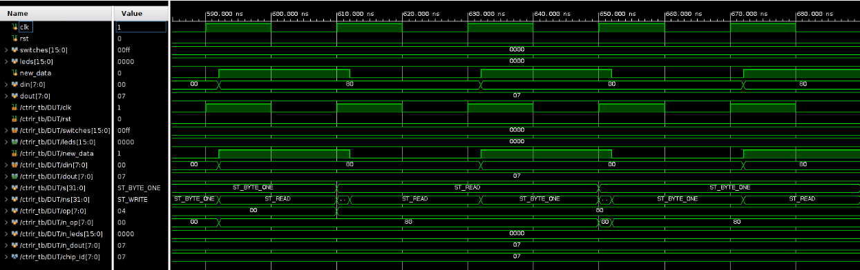
Read Sequence
For Reads, the Pi (Master) reads a value from the Basys3 (slave) using a 2-byte sequence. The first byte sent is the address, with R/W = 1. The Basys3 responds back with the desired data on the second byte. For Reads, the Basys3 can respond back with any values (including 0) for the first byte while the Pi can transmit any value for the second byte. Both unneeded bytes are ignored.
Explanation of Signals
| SIGNAL | Explanation |
|---|---|
clk |
The Basys3’s 100MHz clock |
rst |
The Basys3’s reset signal |
switches[15:0] |
The digital input from the Basys3’s switches. There are 16 switches. |
leds[15:0] |
The digital output to the Basys3’s LEDs. There are 16 LEDs. |
new_data |
This signal indicates new data has arrived from the SPI interface. It should be high for 1 cycle to indicate new data from SPI. It is connected to the SPI’s done signal. |
din |
This is the SPI’s 8-bit parallel received data (MOSI) coming into the Controller. It is used to receive data from the Raspberry Pi. new_data should be high for 1 cycle to indicate valid data on din. |
dout |
This is the Controller’s 8-bit parallel transmit data going to SPI transmit (MISO). It is used to drive new data back to the Raspberry Pi. |
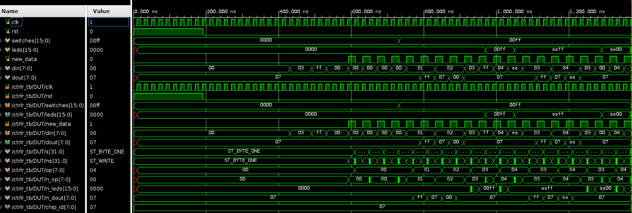
Example Waveforms
Overall Waveform
Read Waveform
Write Waveform