ENGR210
Project 7: 2-Bit Saturating Counter
Due: Wednesday April 2nd
Table of Contents
Overview
In this lab you practice designing simple state machines by implementing a 2-bit saturating counter.
Background
Saturating Counters
A 2-bit saturating counter is a logic block that is commonly used in modern computers for predicting the outcome of branch instructions. (Don’t worry, you don’t need to know about branch prediction for this project).
Such a counter is defined as follows:
- It uses two bits to represent an unsigned number. It is capable of counting from 0-3.
- It is capable of counting up (incrementing) or down (decrementing).
- The counter will “saturate” or stay at its current value if asked to increment or decrement out of its range. For example, in this case that means if the counter is asked to count up past 3 it will stay at 3. If it is asked to count down past 0, it will stay at 0.
- A counter with enable can be told to stop counting.
Our device has three 1-bit inputs: rst, enable and up_down and one 2-bit output count.
When enable is 1, an internal counter is to increment if up_down is 1 and decrement if
up_down is 0. When enable is 0, the counter should maintain its current value. When rst
(reset) is 1 the counter should go to 0 no matter what the other inputs might be. All of the above
should happen on each rising edge of the clock.
The output count should match the internal count value of the saturating counter.
State Machine Verilog Template
Building state machines in Verilog requires closely following a special form , or template, that we have demonstrated below. Be warned: the tools do not enforce this template, it is up to you to write your code correctly!
Here is a simple state machine with one input, x, and two outputs, foo and bar. The inputs are shown in red and the outputs are blue.
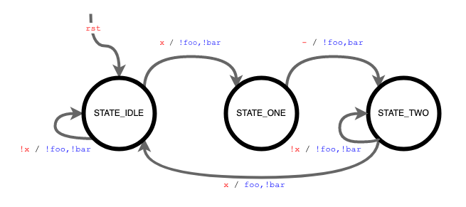
Notice that the outputs bar and foo are set differently. The value of bar can be assigned
based entirely on the current state (STATE_ONE), making it a Moore-type output. The value of
foo requires both state (STATE_TWO) and the input (x), making it a Mealy-type output.
A second interesting note is that two of the states, STATE_IDLE and STATE_TWO, have a
guard to control their state transitions. If x is 0 (shown as !x) the state remains unchanged. If
x is 1 (or just x), then the state transitions on the next clock edge. STATE_ONE does not have
a guard (shown as -). This means it always transitions to the next state on the clock edge.
The Verilog implementation of the state machine is provided below.
module SimpleStateMachine(
    input clk, // clock signal
    input rst, // reset signal
    input logic x, // input signal
    output logic bar, // Moore-type output
    output logic foo // Mealy-type output
);


    //STATE NAMES
    // States can be named whatever you want.
    enum { STATE_IDLE, STATE_ONE, STATE_TWO } state, nextState;

    //sequential block, uses Flip-Flops
    // This always uses Non-Blocking (<=) assignments
    always_ff @(posedge clk) begin
        //reset is the only if() case we suggest in always_ff
        if (rst)
            state <= STATE_IDLE; //add a reset case
        else
            state <= nextState; //non-blocking
    end

    //combinational logic block
    //This always uses blocking (=) assignments
    //You need a default value for everything assigned
    // to avoid inferring a latch
    always_comb begin

        //defaults
        // Don’t forget these!
        // Otherwise you will end up with a latch
        nextState = state; //DO NOT FORGET DEFAULTS
        bar = 'h0; //DO NOT FORGET DEFAULTS
        foo = 'h0; //DO NOT FORGET DEFAULTS

        case(state)
            STATE_IDLE:
                //only transition to STATE_ONE if x is true
                if (x)
                nextState = STATE_ONE; //blocking
                else //optional, handed by default
                nextState = STATE_IDLE; //blocking
            STATE_ONE:
                nextState = STATE_TWO; //blocking
                bar = 'h1; //dependent on only state, not input
            STATE_TWO: begin
                if (x) begin
                    nextState = STATE_IDLE; //blocking
                    foo = 'h1; //dependent on state + input
                end else begin //optional
                    nextState = STATE_TWO;
                    foo = 'h0;
                end
            end
            default: nextState = STATE_IDLE; //case-default
        endcase
    end
endmodule
Testbenches for Sequential Logic
When constructing testbenches for sequential logic, you may find the @(negedge clk)
formulation helpful. This will execute the simulation until the next falling edge of the clock
signal. At this point, all the output signals should be stable, allowing you to test them without
having to know the exact #delay values necessary. With this you can skip forward a
considerable time in the simulation. An example testbench for the above state machine is given
below.
`timescale 1ns / 1ps
module testbench;

    logic clk, rst, x;
    wire bar, foo;

    SimpleStateMachine ssm0(
        .clk,
        .rst,
        .x,
        .bar,
        .foo
    );

    task test_logic( input barT, fooT);
        #1 //let input changes settle
        assert( bar == barT) else $fatal("Bad bar");
        assert( foo == fooT) else $fatal("Bad foo");
    endtask

    //inverts the clock signal for 100MHz clock
    always #5 clk = ~clk;

    initial begin
    // set initial values for clk and reset
    // Always start with rst = 1 for at least 1 clock cycle

    clk = 0;
    rst = 1;
    x = 0;

    $monitor ("clk:%b rst:%b x:%b foo:%b bar:%b", clk, rst, x, foo, bar);

    // wait a few clock cycles
    // and then clear reset
    for (int i = 0; i < 8; ++i)
        @(negedge clk);

    $display(" transition to STATE_ONE");
    rst = 0;
    x = 1;
    test_logic ( 'h0, 'h0); //mealy-type test
    @(negedge clk);
    test_logic ( 'h1, 'h0); //moore-type test

    $display(" transition to STATE_TWO");
    x = 0;
    test_logic ( 'h1, 'h0); //mealy-type test
    @(negedge clk);
    test_logic ( 'h0, 'h0); //moore-type test

    $display(" stay at STATE_TWO");
    x = 0;
    test_logic ( 'h0, 'h0); //mealy-type test
    @(negedge clk);
    test_logic ( 'h0, 'h0); //moore-type test

    $display(" transition to STATE_IDLE");
    x = 1;
    test_logic ( 'h0, 'h1); //mealy-type test
    @(negedge clk);
    test_logic ( 'h0, 'h0); //moore-type test

    $display(" stay at STATE_IDLE");
    x = 0;
    test_logic ( 'h0, 'h0); //mealy-type test
    @(negedge clk);
    test_logic ( 'h0, 'h0); //moore-type test

    $display("@@@Passed\n");
    $finish;

    end
endmodule
Assignment Description
For this assignment, you will create and demonstrate a saturating counter.
Saturating Counter
Your first task is to create a Verilog file named saturating_counter.sv with a module defined as follows:
module saturating_counter(
input clk,
input rst,
input enable,
input up_down, //1 for up, 0 for down
output logic [1:0] count
);
This module should implement a saturating counter as described above.
Debouncing
Sometimes digital buttons (like on the Basys3) don’t go straight between logic values, but instead “bounce” around while you are trying to change them. More Information about Bouncing
Please add this Verilog module to your project to help “debounce” incoming signals.
Top-Level
Please use the following top.sv. It maps reset to btnC, up_down to sw[0], and enable
to btnD. It also debounces and limits the enable signal.
`timescale 1ns / 1ps

module top (
    input CLK100MHZ, //clk
    input btnC, //reset
    input btnD, //enable
    input [15:0] sw,
    output logic [15:0] LED
);

wire clk = CLK100MHZ;
wire rst = btnC;
wire stable;
logic enable;
wire [1:0] count;

// Debounce our incoming signal
debounce db0 (
    .clk(clk),
    .rst(rst),
    .bouncy(btnD),
    .stable(stable)
);

// Then limit enable high to 1 clock cycle
enum {ST_IDLE, ST_WAIT} state, nextState;

always_ff @(posedge clk) begin
    if (rst)
        state <= ST_IDLE;
    else
        state <= nextState;
end

always_comb begin
    nextState = state;
    enable = 'h0;
    case (state)
    ST_IDLE: begin
        if (stable) begin
            enable = 'h1;
            nextState = ST_WAIT;
        end
    end
    ST_WAIT: if (!stable) nextState = ST_IDLE;
    endcase
end

//finally our saturating counter
saturating_counter sCnt0(
    .clk(clk),
    .rst(rst),
    .enable(enable),
    .up_down(sw[0]),
    .count(count)
);

//decoder for the output
always_comb begin
    LED = 16'h0;
    LED[count] = 1'h1;
end

endmodule
Testbench
For this project, you only need to create a testbench for your saturating counter. It should be
named saturating_counter_tb.sv.
Remember to select “System Verilog” from the “File Type” drop-down menu.
MAKE SURE YOU HAVE “$display(“@@@Passed”);” AT THE END OF YOUR TESTBENCH! AND $fatal IN THE APPROPRIATE SPOT! Otherwise some bugs may not pass!
Constraints
We recommend you copy the default constraints file from here:
You will also need to reconfigure your file to align with the top-level module declaration. The names should line up properly by default.
Evaluation
Autograder (70%)
Log on to Autograder and submit your code as per Project 1.
You should submit:
- saturating_counter.sv
- saturating_counter_tb.sv