ENGR210
Project 5: Demultiplexer
Due: Wednesday March 4th
Table of Contents
Overview
For this project, you will design and implement a 3-to-8 Demultiplexer. Demultiplexers help control the logical flow of the digital circuit, and are used in addressing memory and many types of data communication.
Background
To understand demultiplexers, one should first understand a decoder.
Decoder
A decoder is a combinational circuit with n inputs and 2 n^ outputs. For each combination of inputs, one and only one output is logic 1, while all the other outputs are logic 0. For example, a decoder with 2 inputs {a, b} will have 4 outputs {d0, d1, d2, d3}. This circuit is also sometimes called a “ one-hot “, as only one of the outputs is ‘1’ (or hot) at a time.
The truth table for the decoder is shown below.
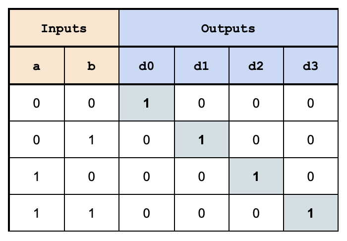
As each output is ‘1’ for only a single combination of inputs, a boolean expression that produces
a particular output can be constructed by testing for the specific input combination. For
example, output d1 is logic 1 if and only if:
a = 0
b = 1
Thus, we can express d1 as a boolean logic equation:
d1 = ~a & b
This corresponds to line number 3 in the above truth table (reproduced below):
| a | b | d1 | Boolean Expression: |
|---|---|---|---|
| 0 | 1 | 1 | d1 = ~a & b |
We can define the d0 through d3 using a set of boolean logic equations:
d0 = ~a & ~b
d1 = ~a & b
d2 = a & ~b
d3 = a & b
Note that the notations “~a”, “a’”, and “ā” are all logical equivalents of the same “NOT(a)”.
Now let’s write some Verilog for that:
module 2_to_4_decoder(
    input a, b,
    output d0, d1, d2, d
);

    assign d0 = ~a & ~b;
    assign d1 = ~a & b;
    assign d2 = a & ~b;
    assign d3 = a & b;

endmodule
We can also represent the same 2-input decoder using a circuit schematic, shown below. If you
trace the wires (green lines) you will see the d1 is again equal to ~a & b.
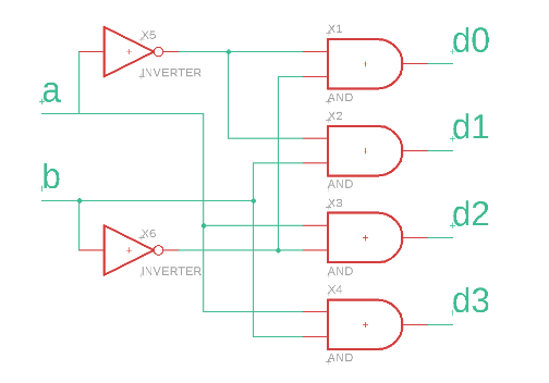
Notice this is the exact same combination of NOT and AND that is expressed in the boolean
equations.
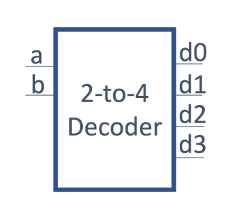
Block Diagram
We can abstract our decoder into a “block” that only shows the inputs and outputs. This will make it easier to use this block later. The inputs are on the left and the outputs are on the right.
Demultiplexer
A demultiplexer is a combinational circuit with 1 data input, n select inputs and 2n outputs. For
each combination of select inputs, the data is transferred to the selected output, while the other
outputs are 0. It is very similar to a decoder, except the output signal is dependent on an
additional input, rather than always fixed to ‘1’.
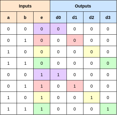
The truth table for a 2-to-4 demultiplexer is shown below. It has 1 data input (e), 2 select inputs
(a and b), and 4 outputs (d0 - d3). The ‘e’ signal is used to ‘e‘nable the selected output
signal. With a demultiplexer, when a = 1 and b = 1, the input e is transferred to the output
d3, while other outputs are 0. This is illustrated with the different colors in the truth table below.
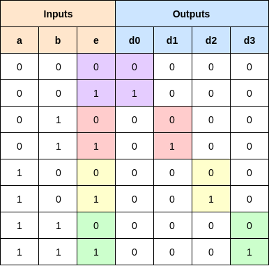
We can again express the outputs as a boolean equation. For example, d1 = 1 requires ~a &
b & e. We express that as:
d1 = ~a & b & e;
Now let’s rearrange the Demultiplexer’s truth table a little. This is the exact same table, just with the rows re-arranged:
What we see is that if e==0 all of the outputs are always 0. If e==1, then the outputs match
the decoder exactly. So, that suggests we can use the decoder to generate some of the signals
required for the demultiplexer.
Verilog Submodules
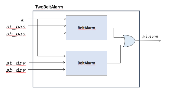
Submodules in Verilog allow you to use smaller modules as building blocks for constructing more complex modules. Recall from the lecture that we can construct a TwoBelt Alarm system by creating two BeltAlarm submodules, as shown below.
In Verilog, we recommend using this method to construct submodules:
SubModuleName SubModule_InstanceName (
    .subModuleVariableName1(localVariableName1),
    .subModuleVariableName2(localVariableName2)
);
SubModuleName is the name as it appears in the submodules verilog file. It will be the same
for all instances of the submodule. SubModule_InstanceName is the name given for a
particular submodule instance. You can instantiate multiple of the same submodules, but they
must have different InstanceNames. subModuleVariableNames signals must match
those given in the submodule’s verilog file. localVariableNames signals must match a
signal in the current module (not the submodule).
If BeltAlarm looks like this:
module BeltAlarm(
    input k, p, s,
    output alarm
);
    assign alarm = k & p & ~s;

endmodule
Then you can create a TwoBeltAlarm by instantiating two BeltAlarm modules as shown
below. Notice that there are two BeltAlarm modules, but they both have different names,
ba_drv and ba_pas. Also, their output is OR‘ed together to form the output of the overall
TwoBeltAlarm module
module TwoBeltAlarm(
    input k, st_pas, sb_pas,
    input st_drv, sb_drv
    output alarm
);
    wire al_pas, al_drv; //intermediate wires

    //submodules,
    BeltAlarm ba_drv(.k(k), .p(st_drv),
    .s(sb_drv), .alarm(al_drv) );
    BeltAlarm ba_pas(.k(k), .p(st_pas),
    .s(sb_pas), .alarm(al_pas));

    assign alarm = al_pas | al_drv;

endmodule
As an optional optimization, if the name inside the parentheses matches the name outside the parentheses, like .k(k), you can skip the parentheses, and just write the name, like .k. With the optimization, our verilog looks like this:
module TwoBeltAlarm(
    input k, st_pas, sb_pas,
    input st_drv, sb_drv
    output alarm
);
    wire al_pas, al_drv; //intermediate wires

    //submodules,
    BeltAlarm ba_drv(.k, .p(st_drv), // .k optimized
    .s(sb_drv), .alarm(al_drv) );
    BeltAlarm ba_pas(.k, .p(st_pas), // .k optimized
    .s(sb_pas), .alarm(al_pas));

    assign alarm = al_pas | al_drv;

endmodule
Tasks in a Testbench
Using tasks to create an exhaustive testbench will prove useful as the course projects increase in difficulty. You may wish to use tasks in this project to begin understanding how they work as well as their purpose, however it is not required.
Tasks make your testbench code cleaner to read and easier to debug.
To use a task you must first define it, here you declare the inputs and outputs of the task, any operations it should do, and assert statements for any output you would like to check. Then you can call the task. For more details on how to use tasks check this link: Nandland
//Task Declaration

task task_name;
    input a,b;
    output outData;

    //operations/algorithms
    //assert to check output
endtask

//Using a task
initial
    begin
    //your testcode here!
    //set input for task
    my_and(1,0,0);
    #1;
    my_and(0,1,1);
    #1;
end

endmodule
Here’s an example of a task you might find helpful for this project. This will set “test” values for
a,b,c, and e. It will then test d0-d3 against d0T-d3T to ensure the output is as expected.
task demux_test;
    input aT, bT;
    input d0T, d1T, d2T, d3T;

    #5
    a = aT; b=bT;
    #5
    assert( ( d0 == d0T ) && ( d1 == d1T ) &&
    ( d2 == d2T ) && ( d3 == d3T ) )
    else $fatal(1,"demux0(%b,%b) failed!", a, b);
endtask
You can call a task from within your initial block just like it’s a C function
initial
begin

    //your testcode here!
    $monitor("%h%h%h%h", d0,d1,d2,d3);

    demux_test (0,0, 0,0,0,0);

    $display("@@@Passed");

    $finish;
end
Assignment Description
For this assignment, you will - create a 3-8 decoder - use your decoder as a submodule in a 3-8 demultiplexer - create corresponding testbenches
Please refer to this tutorial for setting up Vivado as you follow along! Vivado Tutorial
Decoder
First, start by creating a SystemVerilog file named decoder.sv defined as follows:
module decoder(
    input a, b, c,
    output d0, d1, d2, d3, d4, d5, d6, d7
);
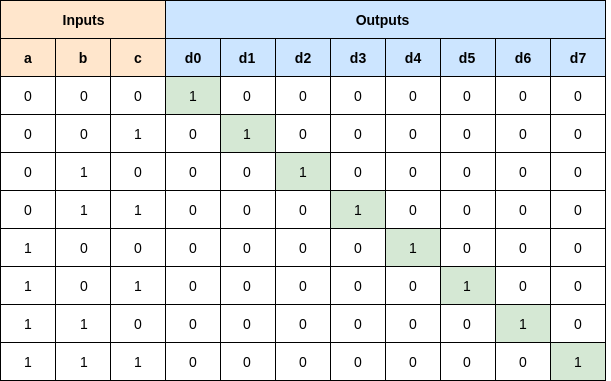
You will need to assign the correct expressions for the outputs d0-d7 in a similar pattern as the
2-4 decoder of the Background section. For example, d0 should be active when
a=0,b=0,c=0, d1 should be active when a=0,b=0,c=1, and d7 should be active when
a=1,b=1,c=1. The truth table for the decoder is provided below:
Demultiplexer
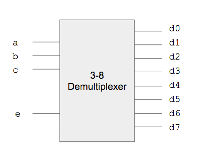
Now create a demux.sv that will serve as your demultiplexer by including the e signal.
module demux(
    input a, b, c,
    input e,
    output d0, d1, d2, d3, d4, d5, d6, d7
);
You will now need to instantiate a decoder submodule within your top-level demultiplexer module. See the Background section for an example. Additional signals internal to your demultiplexer can be created with the wire command as follows:
    wire wire1; //declare a wire
    assign wire1 = 'h1; // assign to 1
    wire wire2 = 'h1; //declare and assign
Your demultiplexer module will need to modify the outputs for the decoder’s d0-d7 signals for
its own d0-d7 outputs. Remember the corresponding d output should be 0 when e==0, and
the same as the original decoder when e == 1.
Top
Please use the following top.sv. This uses arrays, which we will discuss more in class later.
`timescale 1ns / 1ps

module top(
    input [15:0] sw,
    output [15:0] LED
);

demux d0 (
    .a(sw[0]),
    .b(sw[1]),
    .c(sw[2]),
    .e(sw[4]),
    .d0(LED[0]),
    .d1(LED[1]),
    .d2(LED[2]),
    .d3(LED[3]),
    .d4(LED[4]),
    .d5(LED[5]),
    .d6(LED[6]),
    .d7(LED[7])
);
    assign LED[15:8] = 'h0;

endmodule
Testbenches
You will need to create two testbenches to test your code, one for decoder and one for demux.
The first testbench should be named decoder_tb.sv. Remember to select “System Verilog”
from the “File Type” drop-down menu. You can use the following starter code:
`timescale 1ns/1ps

module decoder_tb;

    logic a, b, c;
    logic d0,d1,d2,d3,d4,d5,d6,d7;

    decoder dec0 (
        .a(a),
        .b(b),
        .c(c),
        .d0(d0),
        .d1(d1),
        .d2(d2),
        .d3(d3),
        .d4(d4),
        .d5(d5),
        .d6(d6),
        .d7(d7)
    );

    task decoder_test;
        input aT, bT, cT;
        input d0T, d1T, d2T, d3T, d4T;
        input d5T, d6T, d7T;
        #5
        a = aT; b=bT; c=cT;
        #5
        assert( ( d0 == d0T ) && ( d1 == d1T ) &&
        ( d2 == d2T ) && ( d3 == d3T ) &&
        ( d4 == d4T ) && ( d5 == d5T ) &&
        ( d6 == d6T ) && ( d7 == d7T ) )
        else $fatal(1,"dec0(%b,%b,%b) failed!", a, b, c);
    endtask

    initial
    begin
        a = 0; b = 0; c = 0;
        #10

        $monitor("%h%h%h%h%h%h%h%h", d0,d1,d2,d3,d4,d5,d6,d7);
        decoder_test(0,0,0, 1,0,0,0,0,0,0,0);

        //more test cases here!

        $display("@@@Passed");
        $finish;

    end
endmodule
The Second test bench should be named demux_tb.sv Remember to select “System Verilog”
from the “File Type” drop-down menu. You can use the following starter code:
`timescale 1ns / 1ps
module demux_tb;

    logic a, b, c;
    logic e;
    wire d0,d1,d2,d3,d4,d5,d6,d7;

    demux demux0 (
        .a(a),
        .b(b),
        .c(c),
        .e(e),
        .d0(d0),
        .d1(d1),
        .d2(d2),
        .d3(d3),
        .d4(d4),
        .d5(d5),
        .d6(d6),
        .d7(d7)
    );

    initial
    begin

        //your testcode here!

        $display("@@@Passed");
        $finish;

    end
# endmodule
Your testbench should ensure the correct output for all 16 possible input combinations of a, b,
c, and e. Recall, you can use the following verilog line to test a signal:
assert( led == 0) else $fatal(1, "led==0 Failed");
We encourage you to use tasks to aid in testing.
If you miss an input combination, the autograder will likely detect it during testing.
Constraints
You will also need to reconfigure your constraints file so it uses the correct assignments of switches and LEDs. Rather than writing your own, we recommend you copy the default constraints file from here:
And edit it for our needs. Specifically, you will need to uncomment the appropriate line to enable the various switches and leds needed.
Evaluation
The evaluation will have two steps:
- Submit your source code and testbench to the autograder.
- Synthesize your design, download it to the FPGA and do a demonstration for the TA.
Autograder
To submit your code,
- Follow the above link to the Autograder website.
- Log on using your @IU.edu email address
-
You should now be at a page that looks something like this:
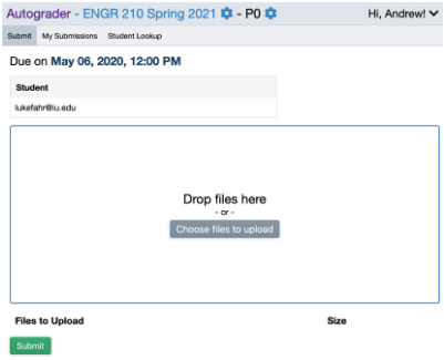
-
Drag or upload the files listed below into the submission window. These files can be found under the sources (
.srcs) subfolder in your Vivado Project’s build folder. - You should submit:
decoder.svdecoder_tb.svdemux.svdemux_tb.sv
- Click Submit
-
You should now be taken to the ‘My Submissions’ window, where the results of your submissions will be shown shortly. It should look something like this:

- This page will display the score for each of the modules that are tested as well as an overall score.
MAKE SURE YOU HAVE “$display(“@@@Passed”);” AT THE END OF YOUR TESTBENCH! AND $fatal IN THE APPROPRIATE SPOT! Otherwise some bugs may not pass!
Demonstration (30%)
Program your FPGA with your demultiplexer and demonstrate your working system to the TA. You will not receive full points until the TA has approved your demonstration.
Version: E210 SP’2024