ENGR210
Connecting the ADXL343 Accelerometer board to the PI
Project 2
Due: Sunday, February 1st
Overview
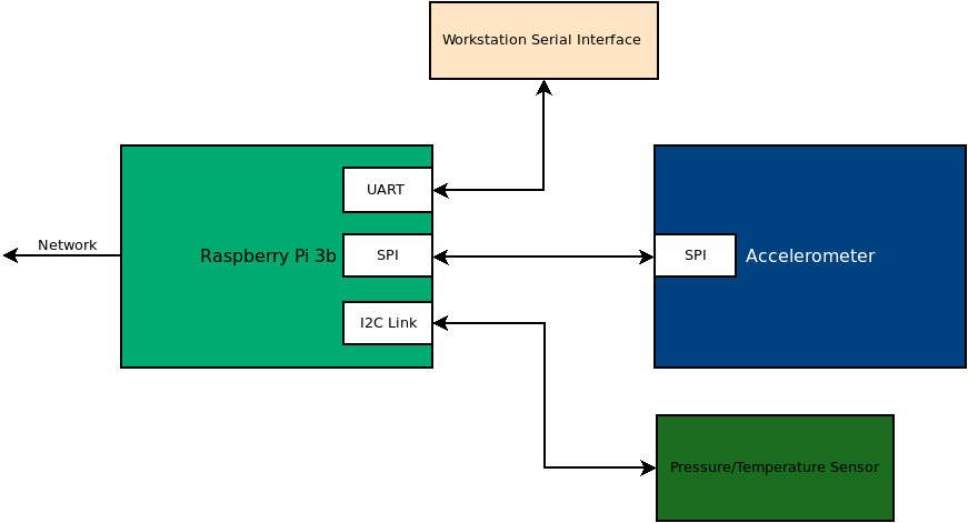
In this project, you will be connecting an accelerometer board to the Raspberry Pi. In the last lab, we used I2C to talk to the pressure sensor. In this lab, we are going to be using Serial Peripheral Interface (SPI) to connect to the ADXL343 accelerometer. You will be creating a python class that enables the raspberry pi to interact with the accelerometer.
Resources
Connecting the sensor board
You will be adding the accelerometer to the same breadboard as the pressure sensor. Do not change the connections to your pressure sensor. At the end of this lab, you should have both sensors wired and functional.
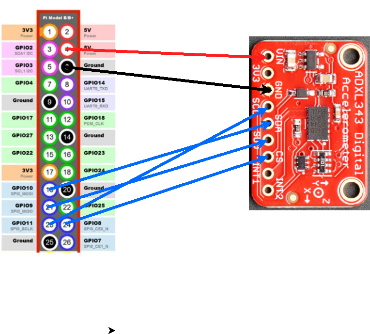
MAKE SURE YOUR WIRING IS CORRECT, THE IMAGE SHOWN DOES NOT SHOW THE WHOLE PI’s PINOUT. COUNT FROM THE TOP PIN NOT THE BOTTOM. IF DEVICE ID IS NOT FOUND THIS MAY BE YOUR ISSUE
| Raspberry Pi Pin | ADXL343 Board |
|---|---|
| 5V | VIN |
| GND | GND |
| Pin 19 (SPI MOSI) | SDA |
| Pin 21 (SPI MISO) | SDO/ALT ADDR |
| Pin 23 (SPI SCK) | SCL |
| Pin 24 (SPI CE0) | CS |
Python Class
Similar to the LPS331 class that you wrote for project 1, you are going to be writing a class that enables the control of the accelerometer. You will be completing the following class to enable the printing of the floating point x, y, and z accelerations. You will need to refer to the datasheet to complete this work.
You can name the file what you want, but adxl343.py is suggested.
#!/usr/bin/env python3

import spidev
import time
import numpy as np

class adxl343:
    ''' Enables communication between the raspberry pi and the ADXL343 board from Sparkfun '''
    def __init__(self,spi_device=0, ce_pin=0, speed=1000000):
        """
        spi_device: there are two spi ports. It is most common to use port 0.
        ce_pin: there are two CE pins that are automatically controlled by the pi.
        speed: the speed for the spi clock is specified here. used to limit spi speed.
        """
        self.spi = spidev.SpiDev()
        self.spi.open(spi_device, ce_pin)
        self.spi.max_speed_hz = speed   # Sets the maximum speed of the SPI link
        self.spi.mode = 0b11            # Sets the spi clock phase and polarity to mode 3
        time.sleep(0.5)
        if self.get_device_id() == '0xe5':
            self.enable()
            print("found ADXL343")
        else:
            print("Device ID Incorrect")

    def read_register(self, address):
        address = address | 0x80                     # Set the read mode
        read_bytes = self.spi.xfer2([address,0x00])  # Send the register address and a dummy byte to clock back data
        return (read_bytes[1])

    def write_register(self, address, data):
        self.spi.xfer2([address,data])
        return(0)

    def enable(self):
        """ Set the measure bit in the POWER_CTL Register to enable sensor """
        pass

    def get_device_id(self):
        """ Read the DEVID register to get back the value of the register"""
        """ Function should return a string that is the output of running the hex function on returned byte"""
        pass

    def read_x_axis(self):
        """ Read the two bytes for the axis, return a floating point g value on a +/-2g scale. """
        pass

     def read_y_axis(self):
        """ Read the two bytes for the axis, return a floating point g value on a +/-2g scale. """
        pass

    def read_z_axis(self):
        """ Read the two bytes for the axis, return a floating point g value on a +/-2g scale. """
        pass

if  __name__ == "__main__":
    sensor = adxl343()
    while 1:
        print(sensor.read_x_axis(), sensor.read_y_axis(), sensor.read_z_axis())
There should be a scale factor on the documentation that tells you how to convert to g’s.
What to turn in (DUE 2/1 11:59PM)
1) Working code:
- You and your partner should work to complete this module and commit it to your repository. When you are satisfied with the code, go to canvas and submit the commit link.
- You and your partner should also demonstrate your working code (X, Y, and Z measurments changing accurately with movement) to one of the TAs present. Alternatively, a video of your functioning code may be submitted to canvas, but this method of submitting is not recommended unless you are sure of the accuracy of your code.
2) Individual Contributions:
-
List down the accomplishments of each member of the group. You should use a
MarkDowntable for this purpose. The table should be formatted similar to the following:Date Time Contributor Accomplishment 1/11/2024 3:15 pm Nicole Completed the X axis code 1/11/2024 4:30 pm Jesus Completed the Y axis code 1/11/2024 4:45 pm Caleb Completed the z axis code 1/11/2024 5:00 pm Aidan Completed Device ID and Enable code
Both team members should submit to the canvas.